
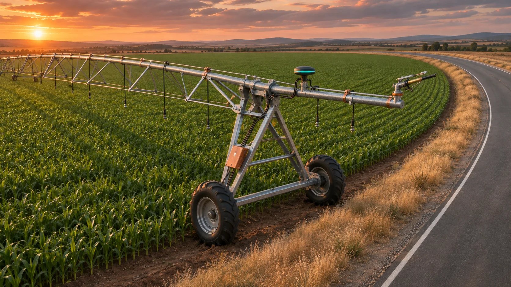
When a center pivot approaches a road, knowing where the end gun is gives you only part of the answer. You also need to know how far its water reaches, how long water continues after an off command and whether the position is current and trustworthy. Verify the spray footprint and shutoff in the field before relying on a new setting.
This guide is for irrigators, farm and grounds managers, and the dealer or controls specialist supporting them. Start with the pivot’s supported end-gun controls. Add position and hydraulic monitoring when the existing panel cannot show which part of the sequence failed.
Start with the approved boundary and pivot panel
Identify the area where water may land. Use a survey or other boundary documentation accepted by the relevant authority. Check the road right-of-way, neighboring land and utility corridors with the appropriate road authority, utility and qualified survey or irrigation professional. A crop edge, fence, aerial image or parcel map can help orient the team. Use verified boundary coordinates for decisions. Assess spray, drift and runoff separately, including the potential for road icing. Confirm applicable constraints before testing.
Many pivot panels already support end-gun on and off sectors. A sector describes where the pivot is allowed to command the gun on around its center. The nozzle’s part-circle arc describes where it throws water relative to the machine. Both matter. Check the installed panel, sprinkler chart, nozzle, booster and valve with the dealer. Record the pivot’s angle reference and verify the relevant approaches in both travel directions. Valley’s manual library covers its panel controls, and its pivot owner’s manual shows why the gun arc is specific to the sprinkler package.
Use the supported panel if its sectors and hardware can handle the site’s verified constraints. Where an irregular boundary makes that difficult, ask the dealer about supported controls or leaving the gun disabled through that part of the field. An external map can help review the evidence before anyone changes settings.
Check position and water reach separately
A multi-band real-time kinematic (RTK) receiver can improve antenna position when its correction link, installation and satellite geometry support it. Record position time, receiver fix type, estimated horizontal accuracy and correction age where the receiver exposes it. RTK fixed, RTK float, a standalone fix and an expired position represent different evidence. A fresh message can still contain a position solution that fails the site’s quality checks. Test for reflections from nearby metal, obstructed sky, link outages and recovery. The u-blox integration manual explains the receiver’s correction and antenna requirements.
The receiver reports its antenna location. Measure the antenna-to-nozzle offset, or lever arm, and account for the pivot heading and any overhang geometry before comparing the gun with the boundary. Verify the offset and orientation at surveyed reference points. Use a common survey datum, coordinate reference system and units for the boundary and the receiver data. Preserve the boundary revision in the test record. NOAA’s National Geodetic Survey explains the reference frames used for surveying and mapping.
Start the spray assessment with the installed nozzle’s performance chart and the confirmed part-circle setting. Pressure, nozzle condition, wind direction, gusts, mounting height and terrain affect where water lands. Compare charts with an approved field observation inside the permitted area. Nelson’s end-of-pivot sprinkler chart shows how published throw and pressure vary by model. Those ranges are planning inputs. A field check still has to account for local wind and installation.
Confirm the gun actually stops delivering water
Capture the panel’s command, booster or valve status if available, and a hydraulic signal on a shared time base. Choose the pressure transmitter’s location with the installer. A gauge upstream of a closed valve can still read normal line pressure while the gun is off. A measurement downstream can show a pressure response or trapped pressure. Select a pressure range that covers normal operation, with a suitable overpressure rating for credible transients. Check wetted materials, mounting and temperature limits. A properly isolated 4–20 mA input is one option for a long cable near motor wiring. Check it against a reference gauge and verify how a broken circuit is reported.
A compatible pulse-output flow meter can add water movement evidence if it is installed on the branch that feeds the gun and can resolve the flow range of interest. Set the pulse scale from the meter documentation, verify it against a reference and check the minimum measurable flow. A pulse gap can also indicate an open circuit or a flow rate below resolution. Record the reason separately when it is known. Pressure and flow can show a hydraulic response. They cannot show where wind carried the water. Use supervised field observations to measure the time from off command to the end of observable discharge, including run-down and any remaining spray that matters at the boundary.
Allow for movement before the water stops
Consider a worked planning example in an interior test area. At one approach, the nozzle moves toward the test boundary at 0.05 m/s. Measured command-to-water-stop time is 14 seconds, so the nozzle travels about 0.7 m during shutoff. The test team carries a 2 m allowance for combined position, boundary and offset uncertainty. It uses a 34 m planning envelope for reach and drift toward that line under the test conditions. Adding the three gives 36.7 m. A proposed off point 35 m from the line is already short in this example, even before any additional margin or required exclusion distance.
This calculation only screens one approach and one set of assumptions. On a real pivot, use the approved geometry for the entire footprint and check both directions, the highest credible approach speed, worst allowed wind and pressure conditions, and the longest verified shutdown time. Treat missing corrections, a stale position, power loss and a missed valve response as explicit failures. A controller should follow the manufacturer-approved local response and independent inhibit. A monitoring display should show an invalid or stale state rather than keeping the last good position on screen as current.
Pilot with dry runs and supervised water tests
If the panel’s logs leave a gap, an ESP32-WROOM-32UE can record GNSS messages from a compatible receiver over UART. It can also log an isolated pressure interface and count conditioned flow pulses with the ESP32 pulse counter. Keep GNSS reception and its antenna separate from the Wi-Fi or optional external sub-GHz telemetry hardware. Size and test the enclosure, power, surge protection and communications for field conditions. Give every event a timestamp and a quality flag. Buffer data through radio outages. Use approved read-only connections and leave the manufacturer’s controls and local inhibit independent of the logger. Espressif’s module datasheet and pulse counter guide document the interfaces.
Use a dry run with the end gun disabled to compare logged positions and panel transitions at known markers. Test stale fixes, loss of corrections, sensor faults, power interruption and recovery in approved conditions. Then have the irrigation team conduct a supervised water test well inside a permitted area before any boundary-adjacent use. Keep personnel out of the moving and pressurized equipment area and follow the site’s electrical and utility clearances. The team can use safe observation points and an approved catch-can layout to check where water lands. University of Georgia Extension’s field testing guide explains collection and the effect of wind on results.
Record the observed wet edge, shutoff times, fault outcomes, conditions tested and who accepted the settings. A pilot earns confidence when the team can reproduce its evidence, explain mismatches and demonstrate the local response to a fault. Recheck after changes to the nozzle, pressure, travel speed, antenna, boundary or controls.